News Center
Connect us
Headquarters address:
5th building,Fulongte Technology park,
Huaxing road,Dalang,Longhua district,518109,
Shenzhen,Guangdong,China
Factory address:
5th building,Fulongte Technology park,
Huaxing road,Dalang,Longhua district,518109,
Shenzhen,Guangdong,China
Phone:
+86-755-29043232
Email:
ZBLED@zhongbo-gd.com
SKYPE:
vitaluo320
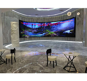
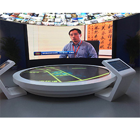
The LED electronic display is a display mode that controls semiconductor light-emitting diodes and is composed of tens of thousands--several hundreds of thousands of semiconductor light-emitting diodes. It can use different materials to produce LED pixels with different colors to display various screens for text, graphics, images, animations, quotes, videos, and video signals. It is widely used in securities trading, financial information display, and airports. Flight dynamic information display, guidance information display for the port station tourists, sports venues, road traffic display, dispatch and command center information display, postal services, telecommunications, mall shopping centers, advertising media new product display and many other types of places.
In practical applications, LED displays inevitably encounter various kinds of failures, causing inconvenience to the application of industrial users and affecting the efficiency of use. This article will summarize some of the common problems and solutions for daily LED display applications.
About the situation where the screen is not bright and how to solve it
With the long-term use of LED electronic display, some failures may occur. If the LED electronic display has the following screen brightness problem, you can check against:
I. The whole screen is not bright (black screen)
1. Detect power supply power.
2. Check whether the communication line is connected and whether it is connected or not. (Sync screen)
3. The sync screen detects whether the green light of the sending card and the receiving card is flashing.
4. Whether the computer monitor is protected or the display area is black or pure blue. (Sync screen)
II. Whole cell board is not bright (black screen)
1. A few boards in a row do not light in the horizontal direction. Check whether the cable connection between the normal unit board and the abnormal unit board is connected; or whether the chip 245 is normal.
2. After several consecutive boards do not light up, check whether the power supply of this column is normal.
III. Lines on the cell board are not lit
1. Check if there is a connection between the line foot and the 4953 output pin.
2. Check 138 is normal.
3. Check 4953 whether it is hot or burned.
4. Check 4953 whether there is a high level.
5. Check whether the 138 and 4953 control pins are connected.
IV. The cell board is not bright
1. Check 595 is normal.
2. Check whether the corresponding module is connected to the upper and lower modules.
3. Check 595 output pin to the module pin is connected.
V. Unit board lack of color
1. Check 245 R.G data for output.
2. Check if the normal 595 output pin and the abnormal 595 input pin are connected
In addition to the screen is not lit, the following is the LED electronic display may appear problems and solutions
01. What could be the cause of the load?
Failure to load may be due to the following reasons: Please check against your actions according to the listed items:
A. Make sure the control system hardware is properly powered up. (+5V)
B. Check and confirm that the serial cable used to connect to the controller is a straight line, not a crossover cable.
C. Check that the serial port cable is intact and that neither end is loose or missing.
D. Compare the LED display control software with the control card of your choice to select the correct product model, the correct transmission method, the correct serial port number, the correct baud rate, and correctly set the control system hardware against the dial switch diagram provided in the software. The address bit and baud rate.
E. Check if the jumper cap is loose or loose; if the jumper cap is not loose, make sure the jumper cap is in the correct direction.
F. If after the above checks and correction still occurs after loading, please use a multimeter to measure if the serial port of the connected computer or control system hardware is damaged. To confirm whether the computer manufacturer should be returned or return the control system hardware.
02. What could be the cause of communication failure?
The reason for the failure to communicate is not the same as the reason for the failure to load. It may be due to the following reasons. Please check against the listed items and your actions:
A. Make sure the control system hardware is properly powered up. (+5V)
B. Check and confirm that the serial cable used to connect to the controller is a straight line, not a crossover cable.
C. Check that the serial port cable is intact and that neither end is loose or missing.
D. Compare the LED display control software with the control card of your choice to select the correct product model, the correct transmission method, the correct serial port number, the correct baud rate, and correctly set the control system hardware against the dial switch diagram provided in the software. The address bit and baud rate.
E.Check if the jumper cap is loose or loose; if the jumper cap is not loose, make sure the jumper cap is in the correct direction.
F. If after the above checks and correction still occurs after loading, please use a multimeter to measure if the serial port of the connected computer or control system hardware is damaged. To confirm whether the computer manufacturer should be returned or return the control system hardware to the test.
03. Why does the system prompt "Please connect the LED display controller"?
Many customers and friends directly download the "LED display control system" from the "Download Center" on the company's website. After installing for 20 minutes, the prompt "Please connect the LED display controller" appears. This is due to the system The reason why the open control system hardware was not detected during the test period.
At this time, please connect one end of the LED display control system hardware you purchased to the computer and the other end to the HUB distribution board. The HUB distribution board's cable socket is connected to the interface of each unit of the LED display.
After the connection is completed, you can enter the "settings" within the "setting screen parameters" set the relevant parameters, complete and then close again after opening the software, then the software will appear above the "connection is successful" words. At this point, the system has detected the display control system hardware and can be used without time constraints.
04. Why does the LED display control system hardware display a few seconds of bright lines or "screen" when it is first powered on?
After connecting the display controller to the computer and the HUB distribution board and display, it is necessary to provide the controller with +5V power for normal operation (in this case, do not directly connect with the 220V voltage). At the instant of power-on, a few seconds of bright lines or “Hua Ping” will appear on the display. The bright line or “Hua Ping” is a normal test phenomenon, reminding the user that the display is about to start normal work. Within 2 seconds, this phenomenon is automatically eliminated and the display goes into normal operation.
05. What does automatic or manual brightness adjustment mean?
Brightness adjustment refers to the adjustment made between the darkest and brightest display on the display. Instead of light regulation.
The automatic brightness adjustment is based on the different brightness that should appear during different time periods and is automatically adjusted by the wide LED display control system to a predetermined brightness.
Manual brightness adjustment refers to that the end user achieves a specified brightness of the LED display through the operation of the LED display control system.
06. Why doesn't the display show above when the controller is all right?
If the controller settings and connection cables are properly connected, sometimes the LED display screen will show no display. Generally, it is caused by one of the following reasons. Please check:
A. LED display is powered on.
B. Whether the connection between the HUB distribution board and the display screen is reversed.
C. Whether the edited and sent program is empty.
07. The unit board appears full screen dark and dark.
A. Visually inspect the power supply cable, the 26P cable between the unit boards, and the power module indicator.
B. Use a multimeter to measure the normal voltage of the unit board, and then measure whether the voltage output of the power module is normal. If not, judge that the power module is bad.
C. Measure the power module voltage is low, adjust the fine-tuning (fine-tuning of the power module near the indicator light) to make the voltage reach the standard.
08. What causes the black screen on the LED display?
In the process of using the control system, we occasionally encounter the phenomenon of black screen LED display. The same phenomenon may be caused by a variety of reasons, and even the darkening of the display screen may vary from one operation to another or from one environment to another. For example, it may be black at the moment of power-on, or it may turn black during loading, or it may be black after sending. If you encounter this phenomenon, please note that you can refer to the following aspects to determine the "failure":
A. Please ensure that all hardware, including the control system, is properly powered on. (+5V, do not connect, connect wrong)
B. Check and re-check if the serial cable used to connect the controller is loose or missing. (If it turns black during the loading process, it may be caused by this reason, that is, it is interrupted during the communication process due to the loose communication line. Therefore, the screen should not be blacked out. Do not think that the display screen is not moving and the wire cannot be loosened. Please Check it out, this is very important for you to solve the problem quickly.)
Service Hotline: +0086-13715391977 +0086-755-29043232 Email: ZBLED@zhongbo-gd.com


